
FEM Analysis
Using the same Matlab script we obtained the static force on the push rod (5900 N) and on the shock-absorber (5100 N), the preload of the spring is 10 mm.
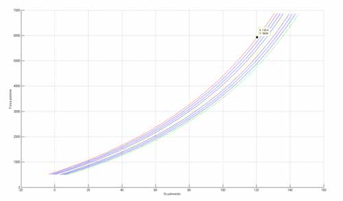
Motion of the swing arm vs force on the push rod
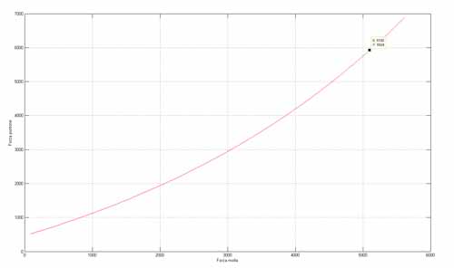
Force on the push rod
vs force on the spring
Alemoto’s staff suggest us to multiply the static forces for a coefficient of 2.5 to get the dynamic ones.
From a catalogue we chose the smallest uniballs that could bear the dynamic forces, we found that we needed an uniball with a 15 mm diameter of the internal hole.
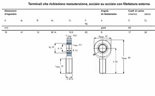
Uniball catalogue
Then we used the FEM module of Catia to test the rods:
The analysis of the push rod didn’t give us any problems, it can easily support the dynamic force considering a yield strength of the steel of 250 MPa (2,5 * 10^8 N/m^2)
FEM analysis on the push rod
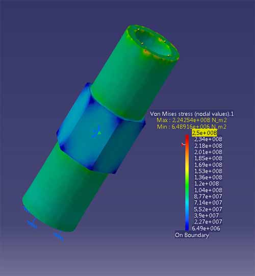
The analysis of the other rod was really more difficult:We chose the “worst” possible situation to do the analysis, when the shock-absorber it’s fully compressed.
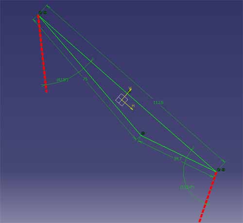
Force vectors on the rod
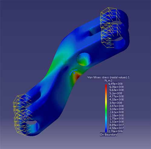
FEM analysis on the rod
The first design (the straight one) had a maximum Von Mises stress in the order of the GPa, so we switched to the second one.
This design had no real problems with the static forces, giving a max stress around 260 MPa, so we can just choose a better steel in order to not increase the weight of the piece.
The analysis with the dynamic forces gave us some problems because Catia needs an isostatic-iperstatic configuration to work.
Clamping to the ground the middle hole (which is the one attached to the frame) leads usto a 650 MPa maximum stress, we can't increase too much the dimension of the piece because of the weight, so our only solution is to use a really good steel with a very high yield strenght.